





Medium Voltage Transformers for Commercial Buildings: Balancing Fire Safety and Space
Select the transformer location and fire-protection concept before comparing kVA ratings. In commercial buildings, a transformer that fits the electrical load can still be a poor selection if its cooling medium, enclosure, access path, or clearance requirements conflict with the building layout. The practical decision is usually between placing a compact dry-type unit inside the building and locating a liquid-filled unit in a dedicated room, vault, exterior enclosure, or separated service area.
A medium voltage transformer for commercial buildings must be evaluated as part of an electrical room, not as an isolated item of equipment. The room must accommodate cable bending radii, medium-voltage terminations, low-voltage busways or switchboards, ventilation routes, door swing, lifting access, and a safe working zone around energized equipment. A transformer footprint shown on a data sheet is therefore only the beginning of the space calculation.
Start with the fire scenario, not the transformer type
Fire safety is shaped by the presence and behavior of combustible liquid, the available separation from occupied areas, the room construction, and the way a fault could develop. Liquid-filled transformers require attention to leakage, fluid ignition characteristics, containment, drainage, pressure relief, and separation from openings or other critical building systems. These factors do not automatically rule out liquid insulation. They determine whether the proposed location and protective design are suitable.
Dry-type transformers remove the liquid-spill issue, which often makes indoor siting easier to justify. Their windings and insulation system still operate at elevated temperatures, however, and their performance depends heavily on clean airflow and controlled ambient conditions. A dry-type design placed in a small, poorly ventilated electrical room can experience excessive heat accumulation even when the transformer capacity appears adequate.
The distinction matters because the same building may support different answers in different areas. A ground-level service yard with access for equipment handling can favor a liquid-filled unit. A transformer room above grade, close to tenant areas or escape routes, often imposes stricter constraints on fire separation, ventilation, noise, and future replacement. The final arrangement must follow the applicable local electrical, building, and fire requirements; those requirements should be confirmed for the actual site rather than assumed from another project.
Combustible fluid is only one part of the assessment
Mineral-oil designs, less-flammable fluids, and natural ester fluids do not create identical planning conditions. Fluid selection affects fire behavior, environmental considerations, dielectric performance, and maintenance practices. It should also be considered alongside the transformer tank design, protection devices, fault duty, and installation environment. A fluid described as less flammable does not eliminate the need for a documented fire strategy or for coordinated room and containment design.
Natural ester fluids such as FR3 vegetable oil can be relevant where a liquid-filled arrangement is needed but the project seeks a different fluid profile from conventional mineral oil. The decision still requires review of the transformer’s thermal design, fluid compatibility, expected ambient temperature range, and the site-specific provisions for containment and fire protection. Treating fluid type as a universal substitute for separation distance is a common source of late-stage design conflict.
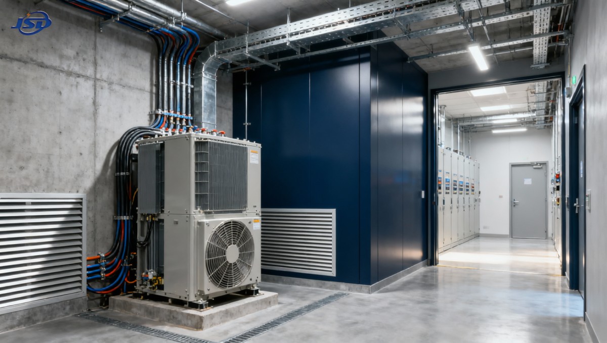
Space is governed by service access and heat rejection
Commercial projects frequently underestimate the operational envelope around a transformer. A unit may pass through the room door during construction but remain difficult to inspect, test, isolate, or replace after adjacent switchgear and cable systems have been installed. Clearance must be reserved for removable panels, cable boxes, radiators where applicable, pressure-relief discharge paths, and the movement of lifting equipment.
Dry-type transformers tend to require a larger ventilated volume around the enclosure because air is their cooling medium. Louvers, intake paths, exhaust paths, and room temperature limits need to be evaluated as a system. Recirculated hot air is especially problematic: an exhaust opening placed too close to the intake can cause the transformer to draw in its own heated discharge. This may raise winding temperature while the room thermometer indicates a less severe average condition.
Liquid-filled transformers transfer heat through the insulating fluid to tank surfaces and cooling equipment. They can offer a compact active assembly for a given application, but external radiator clearance, access to valves and gauges, and containment geometry can increase the total installed area. Outdoor placement avoids consuming interior floor area, yet introduces exposure to weather, vehicle impact, security concerns, and longer low-voltage feeder routes. Those feeder routes can affect voltage drop, conductor cost, and the required space in risers or service corridors.
Capacity selection must reflect the building load shape
Transformer capacity is often selected from a connected-load total with a generic diversity allowance. That approach can miss the load profile that controls transformer temperature. Commercial facilities with lifts, variable-speed drives, data-processing equipment, chargers, HVAC equipment, kitchens, and retail loads may have sharply changing demand and a significant harmonic component. Peak demand duration, simultaneous operation, starting events, and future tenant fit-out need to be examined together.
Harmonic current produces additional heating in windings, leads, and structural parts. A transformer that appears lightly loaded in kVA terms can operate hotter than expected if its load contains substantial nonlinear content. The evaluation should identify likely harmonic sources and confirm whether the proposed transformer design, conductor sizing, neutral arrangement, and protective devices are appropriate for them. Adding capacity without considering harmonics can conceal rather than resolve the thermal cause.
Overload capability also requires careful interpretation. A short-duration overload statement is not permission to use overload as a normal operating condition. It depends on the initial temperature, ambient conditions, cooling state, winding construction, and active temperature monitoring. Repeated overload cycles can have a different effect from an occasional, controlled event because insulation aging is linked to temperature history rather than to a single nameplate figure.
Where a 20 kV utility supply is stepped down to 0.4 kV or 0.415 kV, the selected arrangement should also account for the low-voltage distribution architecture. A transformer located close to the main low-voltage board can reduce the length of high-current secondary conductors. Moving it farther away to improve fire separation may require a more complex secondary route. The electrical room plan must resolve that trade-off before foundations, trenches, and busway supports are fixed.
Reading the specification without overlooking installation limits
For an oil-immersed option, the specification should distinguish between transformer protection and installation protection. An IP-rated enclosure may protect against dust and water ingress, but it does not by itself address room fire separation, oil containment, seismic restraint, or access control. Similarly, a long design-life statement assumes conditions within the stated thermal, environmental, and maintenance boundaries. It should not be used as evidence that inspection access is unnecessary.
An example is the 20kV/0.4kV Oil-Immersed Power Distribution Transformer, available across a 50 kVA to 5000 kVA range and with an FR3 vegetable oil option. For a commercial installation, the relevant evaluation is not simply whether its voltage ratio matches the service. The layout should verify the chosen capacity, 50/60 Hz configuration, cable interface, IP65 enclosure application, fluid containment arrangement, and temperature-monitoring provisions against the actual room or exterior site conditions.
Technical submittals should include outline drawings with all protrusions, not only tank dimensions. Confirm the position of cable entries, radiators, lifting lugs, ground pads, drain valves, temperature indicators, pressure-relief equipment, and terminal clearances. A drawing that lacks these details can lead to a foundation or room layout that is physically workable during installation but impractical during testing or fault investigation.
Insulation system details influence both reliability and room design
Dry-type insulation classes, winding impregnation methods, and enclosure ventilation paths influence how the transformer reacts to dust, moisture, and heat cycling. Surface contamination can reduce insulation performance and restrict airflow. This is particularly relevant in parking structures, loading areas, renovation zones, or rooms that share air paths with dusty service spaces. A nominally indoor location is not necessarily a clean location.
For liquid-filled units, dielectric fluid quality, sealed versus conservator construction, gasket integrity, and moisture control affect long-term insulation condition. Transportation and storage require the same attention. A transformer delivered with impact indicators, pressure records, or shipping restraints should be inspected before energization, and any abnormal indication should be resolved rather than recorded as a minor logistics issue. Damage can remain hidden until it appears as leakage, abnormal gas generation, or a dielectric test concern.
Coordination failures that create avoidable rework
The most expensive errors often occur between disciplines. The electrical layout may show adequate transformer clearance while the architectural plan adds a wall, duct, or door closer to the equipment. Mechanical ventilation may be designed for normal room heat but omit the transformer’s full losses. Civil works may provide a pad but omit a containment curb, drainage path, or cable trench geometry. Each drawing can appear reasonable on its own while the combined installation is not.
- Locate pressure-relief discharge and ventilation openings so they do not direct heat, smoke, or discharge toward circulation areas, sensitive air intakes, or adjacent equipment.
- Confirm the route from delivery point to final position, including floor loading, turns, door openings, overhead obstructions, and the availability of lifting points after construction is complete.
- Coordinate transformer impedance and available fault current with the low-voltage switchboard rating. A change in transformer size or impedance can alter the downstream short-circuit duty.
- Preserve enough cable space to maintain manufacturer bending-radius requirements. Forcing medium-voltage cables into a tight approach can stress terminations and complicate future testing.
- Keep water services, drainage pipes, and condensation sources away from energized terminations and inspection areas. A high IP rating cannot correct poor room drainage or persistent condensation.
Noise deserves the same early coordination. Transformer sound can travel through structural slabs, cable trays, and ventilation ducts, especially when the room borders offices, hospitality spaces, or medical areas. Acoustical treatment may consume space, restrict ventilation, or change access dimensions. It should be designed with the cooling path rather than attached after commissioning complaints arise.
Acceptance should test the installed arrangement
Factory test documentation establishes the transformer’s condition before shipment, but site acceptance must confirm that installation has not introduced a new problem. Visual inspection should verify nameplate data, grounding connections, phase identification, clearances, fluid level where applicable, signs of transport damage, and the correct position of protective devices. Medium-voltage and low-voltage cable terminations require inspection for workmanship, stress-control components, torque records, and phase sequence.
Before energization, confirm that ventilation equipment, alarms, temperature indication, and interlocks function in the way assumed by the electrical design. A room fan that starts only after temperature has already risen substantially may be acceptable in one arrangement and inadequate in another. Likewise, temperature sensors are useful only when alarm thresholds, annunciation paths, and response procedures are defined and tested.
After the initial load period, compare observed temperatures, room conditions, noise, and loading behavior with the design assumptions. This is where a marginal ventilation path, unexpected harmonic heating, or an incorrect tap setting becomes visible. A stable installation is one in which the transformer, its room, and its connected distribution equipment operate within coordinated limits rather than merely passing a no-load energization test.

Get a Quote
Regardless of whether you require general advice or specific support, we are happy to help you.
Send Us Your Inquiry Today

Jinshida Electric remains committed to contributing to global energy development through professional manufacturing and superior service.