





Is a 2000 kVA ONAN Transformer Enough for Your Plant's Peak Demand?
A plant’s monthly electricity report can look comfortably below 2 MW while its transformer still operates close to its limit. Reactive demand, production overlap, large motor starts, and hot afternoons can all change the picture. For technical evaluators, deciding whether a 2000 kVA ONAN transformer is enough means looking beyond the nameplate and understanding what happens during the plant’s most demanding operating periods.
The short answer is yes—if the coincident apparent-power demand, thermal conditions, and transient requirements stay within the transformer’s verified capability. But “below 2000 kVA” is not, by itself, a complete acceptance criterion. The following assessment helps distinguish a sound selection from one that leaves production dependent on ideal conditions.
Start with the load the transformer actually sees
A transformer is rated in kilovolt-amperes, not kilowatts. Its windings carry current associated with both active and reactive power, so a plant’s kW reading cannot be compared directly with a 2000 kVA rating.
For a balanced three-phase load, the basic relationships are:
- Apparent power: S (kVA) = P (kW) ÷ power factor.
- Three-phase current: I (A) = S (kVA) × 1000 ÷ [√3 × line-to-line voltage (V)].
At a power factor of 0.90, a 2000 kVA rating corresponds to 1800 kW. At 0.80, it corresponds to 1600 kW. These are electrical relationships, not guarantees that either load is acceptable under every installation condition.
Consider a hypothetical plant with a measured coincident peak of 1650 kW and a power factor of 0.92. Its apparent demand is approximately 1793 kVA, or 89.7% of the nameplate rating. That looks workable. If a planned production expansion raises the coincident peak to 1850 kW at the same power factor, demand becomes approximately 2011 kVA—already above the rating before considering site-related limitations.
Use power factor measured during the peak, rather than a monthly average. With significant nonlinear loads, use true power factor and measured RMS current; displacement power factor alone can miss the effect of distortion. Check individual phase currents as well, because an acceptable three-phase total can conceal an overloaded phase.
Which “peak” are you trying to accommodate?
A utility billing peak, a production peak, and a motor-starting peak describe different problems. Treating them as interchangeable is one of the easiest ways to select the wrong transformer.
Do not simply add every machine’s nameplate rating. That usually overstates normal coincident demand. Equally, do not apply an optimistic diversity factor without examining the production schedule. Compressors, cooling systems, conveyors, and process equipment may converge precisely when output is highest.
For an existing plant, obtain representative interval data across production cycles and seasons, supplemented by power-quality recordings where necessary. For a new plant, build a load schedule with credible operating combinations, starting sequences, and expansion stages. The goal is to identify the highest realistic demand—not the most convenient average.
What ONAN cooling changes in the capacity assessment
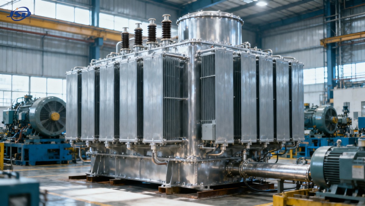
ONAN means oil natural, air natural. Heat moves through natural oil circulation inside the transformer and is released to the surrounding air through the tank and cooling surfaces without forced-air fans. This arrangement avoids fan-related maintenance, but its performance depends on the installation providing suitable heat-rejection conditions.
A 2000 kVA ONAN transformer’s rating applies under its specified service conditions. Confirm those conditions in the manufacturer’s documentation, including ambient-temperature assumptions, altitude, temperature-rise limits, and installation requirements.
Look at the hottest operating combination
A transformer outdoors with unobstructed cooling surfaces does not experience the same environment as one inside a poorly ventilated room. Direct solar exposure, recirculated hot air, restricted clearances, and accumulated dirt can all reduce cooling effectiveness.
Where indoor installation is planned, room ventilation must address transformer losses and other heat sources. The relevant ambient temperature is the air around the transformer, not merely the outdoor weather-station reading. At elevated altitude, reduced air density can also affect cooling and insulation requirements; any adjustments should follow the applicable standard and manufacturer’s guidance.
Duration matters as much as magnitude
A short peak after several hours of light loading is thermally different from the same peak following a heavily loaded shift. Top-oil temperature changes relatively slowly, while winding hot spots can respond faster. Repeated peaks may leave insufficient recovery time.
Do not assume that a fixed overload percentage is universally permissible. If operation above the nameplate rating is proposed, request a loading assessment using the actual duty cycle and ambient conditions, with reference to the applicable IEC 60076-7 or IEEE C57.91 guidance. Acceptability depends on temperatures, insulation aging, accessories, and agreed operating limits—not just whether the transformer avoids an immediate trip.
Three reasons a seemingly adequate rating can still disappoint
1. Motors start successfully on paper but disturb the bus
A transformer may support the running load yet allow excessive voltage depression when a large motor starts. Starting current, acceleration time, transformer impedance, upstream source strength, and cable impedance all influence the result.
The consequences can extend beyond the starting motor: contactors may release, drives may trip, or sensitive process controls may reset. Ask for a voltage-dip assessment using the proposed starting method and the equipment’s allowable voltage limits.
Soft starters, variable-frequency drives, or staggered starts may improve performance. However, their effects must be evaluated in context, including harmonic contribution and process requirements. Transformer impedance also affects fault current, so reducing it to improve starting performance is not a decision to make in isolation.
2. Harmonics add heating that ordinary kVA arithmetic misses
Variable-frequency drives, rectifiers, UPS systems, and other nonlinear equipment can produce harmonic currents. These increase certain winding and stray losses beyond what would occur with sinusoidal current of the same RMS magnitude.
RMS kVA remains important, but it does not fully describe thermal suitability under distorted current. Provide the manufacturer with measured or predicted harmonic spectra, load mix, and operating duty. A harmonic-loss assessment may indicate derating or a design suited to the application. Avoid applying a blanket derating percentage without supporting calculations.
Power-factor correction also needs care. Capacitor banks can interact with network impedance and harmonics, potentially creating resonance. Improving displacement power factor is not automatically the same as reducing every relevant transformer stress.
3. Capacity is adequate, but availability is not
A single transformer sized correctly for normal demand still represents a single point of interruption. If the plant requires continued operation during maintenance or a transformer outage, the decision is partly about system architecture rather than kVA alone.
Two units do not automatically deliver full redundancy. Check whether either unit can carry the required contingency load, which loads can be shed, and how transfers are performed. Parallel operation requires compatibility in voltage ratio, vector group, impedance, tap settings, and protection arrangements.
Should you choose more capacity or reduce the peak?
There is no universal rule that every plant should operate at a particular percentage of transformer rating. A stable, well-characterized load may justify a different margin from a rapidly expanding facility with uncertain process overlap.
Additional capacity becomes more compelling when sustained demand approaches the verified site capability, planned expansion consumes the remaining margin, or operating uncertainty is substantial. It may also be needed when motor-starting performance cannot be resolved economically through control changes.
Still, buying a larger transformer is not always the best first move. Compare production sequencing, appropriate reactive-power compensation, harmonic mitigation, and demand management. A larger unit changes losses, purchase cost, fault levels, and potentially switchgear requirements. Evaluate the complete electrical system rather than treating transformer size as an isolated upgrade.
Keep storage proposals proportional to the plant peak
Battery storage can reduce the demand seen by a transformer, but only when its discharge power, usable energy, inverter rating, and control strategy match the load profile. Energy capacity in kWh should never be mistaken for continuous output power in kW.
For smaller auxiliary applications, Jinshida Electric’s 51.2V Stackable LiFePO4 Energy Storage Battery offers 5.12 kWh per 100 Ah module and a listed expandable capacity range of 5.12–20.48 kWh. CAN/RS485 communication supports integration with compatible energy-storage equipment, subject to configuration verification.
This is not a substitute for a plant-scale transformer capacity upgrade. At the listed 100 A maximum discharge current, one module represents approximately 5.12 kW of nominal DC output before inverter losses and operating limits. Reducing a transformer peak by 200 kW for one hour would require at least 200 kWh delivered on the AC side, plus allowances for losses and reserve. The scale difference should be explicit in any proposal.
Turn the assessment into a defensible specification
Before asking Jinshida Electric Power Technology Co., Ltd. to evaluate a transformer option, prepare a technical package that connects electrical demand with installation conditions. Useful inputs include:
- Supply and output requirements: primary and secondary voltages, frequency, vector group, earthing arrangement, and tap requirements.
- Load evidence: coincident kW and kVA, true power factor, phase currents, seasonal profiles, and peak durations.
- Disturbing loads: major motor ratings and starting methods, nonlinear load details, and harmonic measurements.
- Site conditions: ambient-temperature range, altitude, indoor or outdoor location, ventilation, and cooling clearances.
- System constraints: voltage-drop limits, available fault level, protection coordination, and switchgear ratings.
- Business requirements: expansion plans, acceptable load shedding, maintenance arrangements, and continuity expectations.
Request a documented selection basis covering rated service conditions, losses, impedance, temperature rise, relevant tests, and any required derating. Where assumptions remain uncertain, ask for sensitivity checks—for example, lower power factor, hotter ambient conditions, or greater production overlap.
A 2000 kVA ONAN transformer is enough when the evidence supports it across normal loading, credible peaks, and site conditions. If the decision depends on favorable averages, unverified overload capability, or expansion that has not been included, the selection needs more work. A defensible specification gives the plant something more valuable than a nominal capacity figure: confidence that its busiest shift can run without turning the transformer into the limiting factor.

Get a Quote
Regardless of whether you require general advice or specific support, we are happy to help you.
Send Us Your Inquiry Today

Jinshida Electric remains committed to contributing to global energy development through professional manufacturing and superior service.