





Indoor potential transformers in battery energy storage systems: why fast transient response is critical for state-of-charge estimation
Why indoor potential transformers in BESS aren’t just voltage sensors—they’re SoC gatekeepers
In battery energy storage systems, state-of-charge (SoC) estimation isn’t a theoretical exercise—it’s the operational heartbeat. It determines when to charge, when to discharge, how much power to dispatch, and whether thermal limits are being approached. But here’s what many technical evaluators overlook: SoC algorithms don’t read cell voltages directly. They rely on secondary measurements—typically scaled down via indoor potential transformers—and those transformers must preserve signal fidelity across fast transients, not just steady-state conditions.
Consider a typical BESS event: grid fault clearance followed by rapid re-synchronization. Voltage recovers in microseconds. Harmonic-rich switching events from bidirectional inverters inject high-frequency content above 10 kHz. If the indoor potential transformer’s transient response lags—even by tens of nanoseconds—the captured waveform distorts. Phase shift accumulates. RMS error creeps in. And because SoC estimators (like Kalman filters or adaptive Coulomb counting) integrate voltage over time, small errors compound into meaningful deviations: ±3–5% SoC drift after just a few cycles. That’s enough to trigger conservative derating, misfire safety cut-offs, or miss peak-shaving windows.
Transient response isn’t about speed alone—it’s about fidelity under stress
IEC 61869-3 defines accuracy classes for instrument transformers—but it doesn’t mandate transient response metrics for indoor potential transformers used in BESS monitoring. Class 0.2 or 0.5 accuracy refers to sinusoidal, 50/60 Hz conditions at rated frequency. Real-world BESS operation is anything but sinusoidal. Fast transients expose core saturation limits, winding capacitance effects, and insulation system resonances that standard tests rarely probe.
A transformer with excellent steady-state ratio error can still introduce 2–3° phase lag at 1–5 kHz—a range where inverter switching noise dominates. That lag translates directly into voltage magnitude error when sampled asynchronously by a digital control unit. Worse, some designs exhibit overshoot or ringing during step transitions, creating false zero-crossing detection or erroneous harmonic content interpretation.
At Jinshida Electric, our indoor potential transformers for BESS applications are validated—not just against IEC 61869-3—but against proprietary transient test profiles derived from actual grid-edge inverter waveforms. We measure response to 10–90% rise times under 100 ns, track phase linearity up to 10 kHz, and verify electromagnetic immunity per IEC 61000-4-3 and -4-4. This isn’t compliance theater. It’s built-in resilience for systems where milliseconds matter.
Where indoor potential transformers sit—and why location changes everything
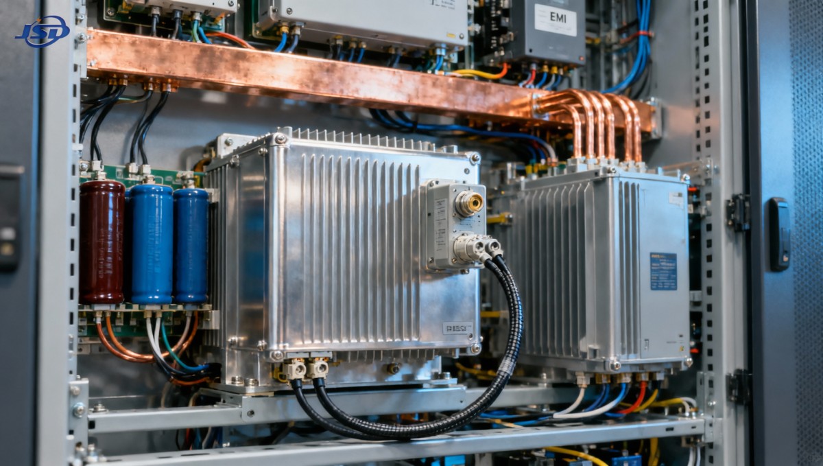
“Indoor” isn’t just about enclosure rating. It signals proximity to power electronics—often within 1–2 meters of medium-voltage inverters, DC-link capacitors, and grounding buses. That environment carries high dv/dt, strong magnetic fields, and ground potential shifts during fault events. An outdoor-rated PT might survive there—but its measurement integrity won’t.
Shielding, winding geometry, and core material all influence immunity. Laminated nanocrystalline cores reduce eddy-current losses at high frequencies. Double-shielded windings suppress capacitive coupling. And careful grounding topology—verified with real-time common-mode current monitoring—prevents induced offsets during fast transients. These details don’t appear in datasheets labeled “Class 0.2.” They emerge only in application-specific validation reports.
Integration isn’t plug-and-play—it’s parameter negotiation
Technical evaluators often assume compatibility between PTs and battery management systems (BMS) or energy management systems (EMS). But mismatched burden ratings, unaccounted-for cable capacitance, or insufficient anti-aliasing filtering upstream of the ADC can negate even the best transformer performance. For example: a 10 m cable run between PT and acquisition unit adds ~1 nF/m of stray capacitance. At 5 kHz, that’s ~30 kΩ impedance—enough to load a high-impedance secondary and skew amplitude response.
Jinshida’s approach treats the PT as part of a sensing chain—not an isolated component. We provide full secondary burden curves, frequency-dependent ratio/phase error plots, and verified interface recommendations for leading BMS platforms. When paired with low-noise, synchronized sampling architectures, our indoor potential transformers deliver sub-0.1% RMS error across 0.1–10 kHz—validated under temperature cycling and humidity stress per IEC 60068-2.
Not every transformer belongs in a BESS cabinet
Some projects default to repurposing general-purpose distribution transformers—like the 30kV/0.4kV Oil-Immersed Power Distribution Transformer—for voltage monitoring. While robust and certified to IEC 60076 and European Ecodesign Tier 2 standards, these units prioritize efficiency (>99%), thermal stability (ONAN cooling), and long service life (>25 years)—not transient fidelity. Their design intent is power delivery, not precision sensing. Using them for SoC-critical measurement introduces blind spots no calibration routine can fix.
That distinction matters most where standards intersect with risk: UL 1973, IEEE 1547-2018, and China’s GB/T 34122 all require accurate voltage reporting during fault ride-through—but they don’t specify how fast the sensor must respond. The gap falls to engineering judgment. And judgment rests on knowing what your transformer actually does—not just what its nameplate says.
Next steps for technical evaluators
If you’re evaluating indoor potential transformers for BESS integration, start with three questions:
- Can the manufacturer supply transient response data—not just steady-state accuracy—across 100 Hz to 10 kHz?
- Is immunity testing performed with representative inverter switching waveforms (not just EMC pulses)?
- Are burden recommendations validated with real cabling and acquisition hardware—not idealized lab setups?
These aren’t checklist items. They’re thresholds. Cross them, and you move from “good enough” to traceable, defensible SoC estimation—where every millivolt counts.

Get a Quote
Regardless of whether you require general advice or specific support, we are happy to help you.
Send Us Your Inquiry Today

Jinshida Electric remains committed to contributing to global energy development through professional manufacturing and superior service.