





Indoor potential transformers: how enclosure ventilation design affects long-term stability at 6.6kV
Why enclosure ventilation isn’t just an afterthought for 6.6kV indoor potential transformers
If your project specifies an indoor potential transformer at 6.6kV—and especially if it’s installed in a compact switchgear bay, a sealed control room, or a high-ambient industrial facility—you’re not just selecting a voltage-sensing device. You’re committing to a thermal management system where airflow design directly determines whether measurement accuracy holds over five years—or drifts measurably by year two.
This isn’t theoretical. At 6.6kV, core losses and winding eddy currents generate steady heat, even under light load. In indoor enclosures—where convection is restricted and ambient temperatures often exceed 40°C—the absence of purpose-built ventilation pathways creates localized hot spots above the magnetic core and around secondary terminals. That heat accelerates insulation aging, shifts dielectric constants in epoxy-resin castings, and introduces phase-angle errors that compound during harmonic-rich operation (common near VFDs, arc furnaces, or rectifier loads). Field data from utility retrofits shows measurement drift exceeding ±0.5% after 18 months in poorly ventilated enclosures—well beyond IEC 60044-2 Class 0.2 tolerance bands.
Three ventilation flaws that look benign on paper—but fail in practice
Most specifications list “IP54 enclosure” or “natural convection cooling” without defining airflow volume, path geometry, or thermal boundary conditions. That leaves critical gaps:
- Asymmetric inlet/outlet placement: A single top-mounted vent with no coordinated low-level intake creates laminar stagnation zones—not bulk airflow. Heat rises, yes—but without directed inflow, it recirculates within the upper third of the enclosure, bypassing critical insulation interfaces.
- Undersized grilles with unaccounted pressure drop: Standard perforated plates reduce effective free area by 60–70%. When paired with internal baffles or cable entries, net airflow can fall below 0.3 m³/min—even when nominal specs suggest adequate ventilation. At 6.6kV, that’s insufficient to offset continuous 8–12 W core loss in typical 50 VA units.
- No thermal derating validation for stacked or wall-mounted configurations: Manufacturer datasheets rarely test enclosures mounted flush against concrete walls or stacked three-high in modular kiosks. In those cases, rear-panel convection is choked, and radiant heat from adjacent equipment raises ambient by 8–15°C. Ventilation designed for freestanding operation becomes functionally inadequate.
These aren’t edge cases. They’re routine installation realities—especially in brownfield upgrades where space constraints force tight integration with existing switchgear.
What “thermally optimized” actually means—beyond airflow charts
A robust ventilation architecture for 6.6kV indoor potential transformers must do three things simultaneously:
First, establish a predictable, directional flow path—from bottom inlet, across core and primary winding base, then upward past secondary terminals and out through top vents—without turbulence-induced hot pockets. This requires computational fluid dynamics (CFD) modeling tied to actual coil geometry, not generic enclosure templates.
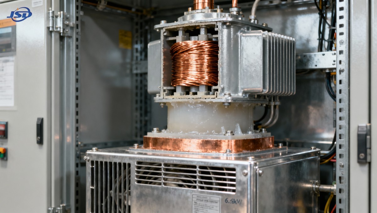
Second, integrate passive thermal mass: copper-clad mounting flanges, thermally conductive potting compounds, and aluminum heat-spreading frames that absorb transient spikes and smooth diurnal temperature swings. This reduces peak thermal stress on resin insulation—where degradation begins long before bulk temperature exceeds limits.
Third, validate performance under real-world derating conditions: 45°C ambient, 95% RH, adjacent to 200 kVA distribution transformers, and with 30 mm cable bundles entering at the base. If testing stops at 35°C lab ambient, field stability remains unproven.
When does ventilation design cross into system-level risk?
Ventilation isn’t only about longevity—it’s a safety and compliance lever. IEC 61869-1 mandates thermal class F (155°C) insulation for indoor instrument transformers rated above 3.6kV. But that rating assumes specified cooling conditions. If enclosure airflow falls short, hotspot temperatures at the core-to-resin interface routinely reach 165–175°C—even when average winding temperature reads within spec. That’s where partial discharge initiates, accelerating insulation breakdown and increasing failure probability during voltage transients.
More quietly, poor ventilation erodes metrological integrity. Dielectric constant shifts in resin under sustained thermal cycling alter capacitance between windings—distorting ratio and phase error characteristics. Unlike power transformers, where load loss dominates heating, potential transformers operate continuously at near-full voltage. So thermal stress is constant, not cyclical. And because they feed protection relays and revenue meters, even 0.15% ratio drift at 6.6kV can trigger nuisance tripping or billing discrepancies across hundreds of downstream circuits.
Practical selection criteria—what to verify before finalizing spec
Don’t rely on “ventilated enclosure” as a checkbox. Ask for:
- CFD simulation reports showing velocity vectors and max hotspot locations at 6.6kV, 100% rated voltage, and 45°C ambient;
- Thermal imaging validation data—not just at rated load, but at 110% voltage (simulating system overvoltage events);
- Derating curves specific to wall-mounted and back-to-back configurations—not just freestanding;
- Insulation life modeling (based on Arrhenius equation) showing projected loss of dielectric strength after 15 years at your site’s worst-case ambient profile.
Also consider material synergy: FR3 vegetable oil—used in some high-reliability distribution transformers like the 10kV/0.4kV Oil-Immersed Power Distribution Transformer—offers superior thermal stability and higher flash point than mineral oil. While not used in potential transformers, its adoption reflects a broader industry shift toward thermally resilient insulation systems—where ventilation isn’t compensation for weak materials, but reinforcement of already robust ones.
The bottom line for project managers
For 6.6kV indoor potential transformers, enclosure ventilation isn’t ancillary engineering—it’s part of the metrological chain. If your project demands stable voltage sensing over a 15–20 year lifecycle, treat ventilation design with the same rigor as turns ratio tolerance or burden calculation. Request thermal validation data tied to your actual installation constraints—not generic lab conditions. And recognize that “standard ventilation” often means “minimum compliant”—not “field-proven stable.” Where measurement integrity impacts protection coordination, energy accounting, or regulatory reporting, that distinction isn’t academic. It’s operational.

Get a Quote
Regardless of whether you require general advice or specific support, we are happy to help you.
Send Us Your Inquiry Today

Jinshida Electric remains committed to contributing to global energy development through professional manufacturing and superior service.