





How Cast Resin Insulation Works in a Three-Phase Dry-Type Transformer
In a humid plant room or a heavily loaded industrial installation, transformer insulation must do more than prevent contact between conductors. Moisture, electrical stress, temperature cycling, and short-circuit forces can weaken the winding insulation system. A three phase cast resin transformer addresses these challenges by encapsulating selected windings in cured resin, creating a solid dielectric barrier that also provides mechanical support.
The essential mechanism is straightforward: resin surrounds the winding conductors and associated insulation, replacing vulnerable exposed spaces with a controlled solid structure. However, resin alone does not establish reliability. Winding geometry, void control, curing quality, cooling arrangements, and verified dielectric performance determine whether the insulation remains effective in service. When comparing equipment, evaluate the complete insulation system rather than treating “cast resin” as a performance guarantee.
Where cast resin fits within the winding assembly
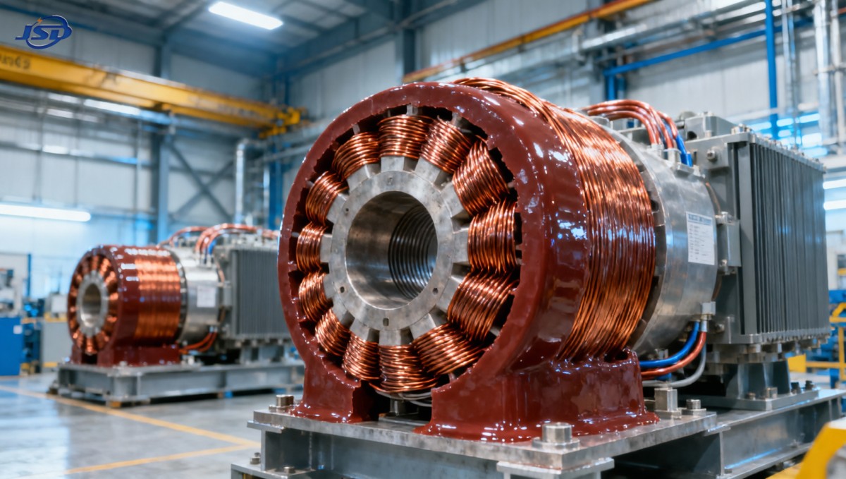
A three-phase dry-type transformer normally has three winding assemblies associated with the three phases. Each assembly contains high-voltage and low-voltage windings, with insulation separating turns, layers, windings, and grounded components. In many cast resin designs, the high-voltage winding is vacuum-cast in epoxy resin, while the low-voltage winding uses a different insulated construction. Some designs encapsulate both; the actual arrangement should be confirmed from drawings and technical documentation.
This distinction matters because an external cast coil does not reveal every internal insulation interface. Turn insulation may include conductor coatings or insulating films. Layer insulation, resin, reinforcing materials, spacers, and air gaps perform different functions. The cast body protects the winding, but it does not replace the clearances required between phases or between live parts and earth.
Air ducts often separate concentric windings or pass through parts of the coil assembly. These passages allow heat to escape by natural or forced air circulation. Filling every available space with resin would not necessarily improve the transformer: it could obstruct cooling or introduce unfavorable mechanical stresses.
Electrical protection depends on field distribution, not thickness alone
During operation, voltage differences exist between adjacent turns, between winding sections, across the high- and low-voltage windings, and from live parts to grounded structures. The insulation must withstand normal operating voltage as well as specified test stresses and transient overvoltages. These stresses are not distributed uniformly throughout the coil.
Conductor edges, winding ends, lead exits, and transitions between materials can concentrate the electric field. Designers manage these regions through conductor shape, insulation dimensions, winding arrangement, and, where necessary, field-control features. Increasing resin thickness everywhere is not a substitute for controlling a localized high-stress region.
Interfaces deserve particular attention. Resin, air, and other insulating materials have different dielectric properties, so their boundaries influence electric-field distribution. An internal gas-filled void can experience greater electrical stress than the surrounding solid insulation. Discharge within that void may gradually damage adjacent material even though the transformer has not suffered an immediate breakdown.
Partial discharge is therefore a key indicator of insulation quality, but not a complete assessment by itself. Its interpretation depends on the applied voltage, test sequence, measurement sensitivity, background noise, and acceptance criteria. A reported value without those conditions provides limited evidence for comparing suppliers.
What vacuum casting and curing actually accomplish
Vacuum casting is intended to reduce trapped gas and help resin penetrate the prepared winding structure. The manufacturing sequence usually includes winding preparation and drying, resin preparation, evacuation, controlled filling, and curing. Exact procedures depend on the resin formulation and coil design; the label “vacuum cast” does not establish that every manufacturer uses equivalent process controls.
Moisture and voids must be controlled before the resin hardens
Residual moisture, trapped air, contamination, or incomplete resin penetration can create weak regions. Drying removes moisture from materials that would otherwise become enclosed. Resin conditioning and degassing reduce entrained gas, while suitable viscosity and filling conditions help the mixture reach narrow spaces without leaving unfilled pockets.
For technical evaluation, useful evidence includes documented material controls, drying procedures, casting parameters, and traceability to production records. A polished exterior cannot demonstrate that the internal winding structure is free from unacceptable defects.
Curing determines more than surface hardness
During curing, the resin forms a cross-linked solid. The cure cycle influences its mechanical properties, thermal behavior, and residual stress. An unsuitable cycle can leave incomplete cure or create excessive stress through shrinkage and uneven temperature distribution. These effects may not be apparent during a visual inspection.
Filled epoxy formulations are commonly used to adjust thermal expansion, mechanical behavior, and processing characteristics. Reinforcement may also support the structure. The appropriate formulation must be compatible with the conductor, other insulation materials, and service temperature range; resin identification alone does not prove that compatibility.
Thermal and mechanical loads act on the same insulation
Resin supports conductors against movement, but it must also tolerate repeated heating and cooling. Copper or aluminum conductors and the surrounding resin expand differently. The resulting stresses concentrate at interfaces, corners, and geometrical transitions. A well-designed coil balances stiffness with resistance to cracking rather than simply maximizing hardness.
Short circuits introduce another load mechanism. Electromagnetic forces can push conductors radially and axially, stressing the cast body, winding supports, and clamping system. Resin contributes to structural integrity, but short-circuit withstand remains a property of the complete transformer assembly.
Heat removal is equally important. Resin conducts heat from internal conductors toward exposed surfaces, while air carries it away. Blocked ducts, poor enclosure ventilation, or excessive ambient temperature can increase winding temperature even when the electrical insulation was manufactured correctly. Thermal aging can then reduce insulation life without any visible initial defect.
- Insulation thermal class: identifies the thermal capability of the insulation system; it is not permission to operate continuously at an arbitrary winding temperature.
- Temperature rise: must be assessed against the applicable requirements and stated cooling conditions.
- Loading profile: harmonic currents, sustained overload, and repeated load cycling can change losses and thermal stress.
- Cooling dependency: distinguish the natural-air rating from any higher rating that depends on fans and functioning controls.
For a renewable-energy installation with changing output or an industrial load with significant harmonics, request a thermal assessment based on the expected duty. Nameplate capacity alone does not describe those operating conditions.
Moisture resistance has practical limits
Encapsulation reduces direct moisture exposure of the embedded winding and can make cast resin equipment suitable for environments where unprotected insulation would be more vulnerable. It does not make the transformer waterproof. Terminals, exposed surfaces, air gaps, and supporting insulation remain affected by installation conditions.
A cold transformer energized after storage can encounter condensation. Dust or conductive deposits on resin surfaces may combine with moisture to create leakage paths and increase the risk of surface tracking or flashover. That mechanism differs from discharge inside a casting void and requires a different corrective response.
The enclosure and room conditions must therefore be considered together. An enclosure may limit access and contamination, but it also restricts airflow. Its protection rating does not establish immunity to condensation, salt deposits, or chemical exposure. Environmental suitability should be checked against the declared service conditions and any specified environmental, climatic, and fire-behavior classifications.
Evidence to request under the applicable transformer standard
IEC 60076-11 is a relevant reference for dry-type power transformers within its scope. Other parts of the IEC 60076 series address subjects such as dielectric tests and short-circuit withstand. Contracts should identify the applicable editions, equipment scope, and acceptance requirements rather than relying on a general statement of IEC compliance.
Also distinguish routine tests performed on the delivered unit from type or special tests supported by representative equipment. Confirm that supporting reports apply to the offered design and rating. A report for a substantially different coil construction may not establish the same behavior for the proposed transformer.
Temporary substations require a separate technology check
Temporary power installations add transport, outdoor exposure, and restricted ventilation to the evaluation. A packaged substation may integrate the transformer, high- and low-voltage switchgear, protection devices, and control systems, but the package description does not identify the transformer’s insulation technology.
The Mobile Temporary Compact Substation, for example, is specified for trailer-mounted or skid-mounted deployment, outdoor installation, and capacities from 500 kVA to 1250 kVA. Its listed cooling method is ONAN, meaning oil-natural, air-natural cooling. It should therefore not be presented as a cast resin dry-type transformer on the basis of the supplied specifications.
For a project that specifically requires cast resin insulation, first confirm whether a suitable dry-type configuration is available and obtain its separate technical documentation. The listed IEC 62271 reference and GB/T 17467 package-substation standard do not replace transformer-specific insulation evidence. Transport restraints, ventilation, clearances, and commissioning checks must also suit the actual transformer installed inside the package.
Interpreting defects and operating symptoms
Different symptoms point toward different mechanisms. Surface discoloration near a terminal may indicate a poor connection or local overheating rather than an internal resin defect. Visible cracking can arise from mechanical damage or thermal stress and requires assessment of its location and depth. A high partial-discharge result may involve internal defects, external discharge, or measurement interference; diagnosis must separate these possibilities.
After safe isolation by qualified personnel, inspections should focus on contamination, blocked cooling passages, damaged leads, loose connections, and changes from the documented baseline. Suspected internal insulation damage requires manufacturer-approved testing. An insulation-resistance measurement alone cannot demonstrate the absence of voids or confirm impulse withstand, and unapproved high-voltage testing can damage the equipment.
The strongest acceptance decision links three things: the winding construction, controlled manufacturing records, and test evidence applicable to the delivered design. Where one is missing, request that specific evidence before approving the equipment. A sound casting process cannot compensate for inadequate clearance, and a successful dielectric test cannot justify operation beyond the documented thermal or environmental limits.

Get a Quote
Regardless of whether you require general advice or specific support, we are happy to help you.
Send Us Your Inquiry Today

Jinshida Electric remains committed to contributing to global energy development through professional manufacturing and superior service.