





Electrical Substation Transformer Design for Solar Power Plant Interconnection
Electrical Substation Transformer Design for Solar Power Plant Interconnection
An electrical substation transformer for solar power plants is a critical link between renewable generation and grid reliability. For project managers and engineering leaders, the right design must balance capacity, voltage matching, protection coordination, efficiency, and long-term operating conditions.
This guide explores the essential design considerations for building safe, high-performance solar plant interconnections that support stable commissioning, compliant grid access, and dependable energy delivery.
For most project teams, the central question is not simply which transformer rating to purchase. It is whether the complete substation design will meet grid requirements without creating avoidable construction, commissioning, or operating risks.
A well-designed interconnection system protects project revenue. It reduces curtailment exposure, prevents expensive redesigns, supports predictable energization schedules, and gives asset owners a stronger foundation for decades of operation.
The most useful design process starts with utility requirements, plant electrical architecture, environmental conditions, and future operating assumptions. Equipment selection should follow those decisions, rather than drive them.
Project leaders should therefore evaluate transformer design as part of the entire grid connection package, including collection circuits, inverter stations, protection systems, switchgear, grounding, communications, and utility metering.
Start With the Grid Connection Requirement
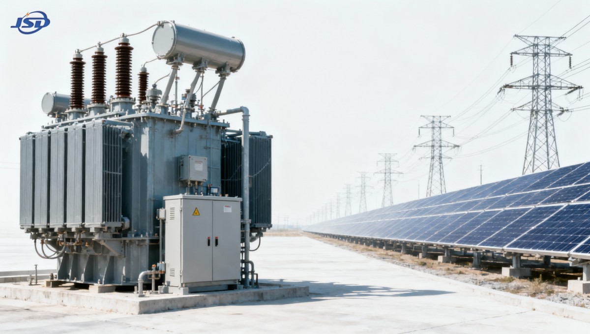
The point of interconnection establishes the fundamental transformer design parameters. Grid voltage, short-circuit level, utility protection philosophy, reactive-power requirements, and fault-clearing performance all influence the selected configuration.
Before finalizing equipment specifications, obtain the latest utility interconnection agreement, preliminary system impact study, and protection requirements. These documents often contain constraints that cannot be solved through transformer selection alone.
Project managers should confirm the required high-voltage connection level early. A solar facility may collect power at medium voltage, then use a main transformer to deliver energy at 35kV, 66kV, 110kV, or higher.
The required voltage ratio must match both inverter output architecture and utility voltage tolerance. A nominally correct ratio can still create operational problems when actual voltage ranges differ across seasons.
Grid operators may require specific transformer vector groups to support grounding, fault detection, or harmonic performance. These requirements should be documented before procurement, especially where multiple inverter blocks share collector feeders.
Short-circuit capacity at the interconnection point also matters. The transformer, bushings, switchgear, cables, and protection devices must withstand available fault currents under the utility’s specified system conditions.
Do not assume that a preliminary grid study remains valid through construction. Network upgrades, nearby generation projects, and utility changes may affect fault levels, voltage control obligations, and protection coordination.
A practical review gate before placing orders is a signed electrical basis of design. It should reconcile utility conditions, plant capacity, transformer data, and protection assumptions in one controlled document.
Size Transformer Capacity for Real Operating Conditions
Transformer capacity should be based on maximum expected AC export, inverter loading behavior, auxiliary consumption, reactive-power obligations, ambient temperature, and the operating margin needed for reliable long-term service.
Using plant DC capacity alone is not sufficient. Solar projects are commonly oversized on the DC side, while the transformer must be evaluated against the maximum simultaneous AC output.
Start with the inverter nameplate total, then account for active-power limits imposed by the grid connection agreement. This establishes the basic export capacity that the substation transformer must support.
Reactive power can materially affect apparent power demand. A plant exporting at a non-unity power factor may require a transformer with significantly higher MVA capacity than its MW export rating suggests.
For example, a 50MW plant required to operate at 0.95 power factor needs approximately 52.6MVA before considering losses, reserve margin, temperature derating, or future expansion.
Ambient temperature and installation conditions can reduce effective capacity. Outdoor transformers in hot, dusty, high-altitude, coastal, or poorly ventilated locations need assumptions that reflect site reality rather than catalog values.
Overload capability deserves careful interpretation. Short-duration emergency loading may be acceptable, but it should not become the assumed normal operating condition for a revenue-generating solar asset.
Where expansion is possible, assess whether a larger transformer, parallel units, or spare bay provisions offer better lifecycle value. The preferred option depends on land constraints, utility approval, and outage tolerance.
Choose Voltage Levels and Vector Groups Deliberately
Solar transformer design often combines low-voltage inverter outputs with medium-voltage collection circuits. The selected voltage levels should minimize losses, simplify cable routing, and remain compatible with locally available protection equipment.
Typical photovoltaic step-up arrangements raise 0.315kV, 0.4kV, or 0.69kV inverter output to 10kV, 20kV, or 35kV collection voltages. Final selection depends on plant scale and regional grid practice.
For inverter station transformers, low-voltage winding voltage must align with inverter operating limits, including voltage ride-through requirements. A mismatch can limit inverter capability during abnormal grid conditions.
Higher collection voltage can reduce current and cable losses, particularly across large sites. However, it may increase equipment cost, insulation requirements, switching complexity, and the need for specialized construction resources.
Vector group selection affects grounding behavior and harmonic circulation. Dyn11 is frequently used where a delta winding helps isolate certain zero-sequence components while providing a grounded neutral on the secondary side.
Yyn0 configurations may suit other system arrangements, but they require a thorough grounding and fault-protection assessment. There is no universally correct vector group for every solar project.
Tap changer selection also requires a project-specific decision. Off-circuit taps may be suitable for stable utility voltage conditions, while on-load tap changers can support more active voltage regulation needs.
Specify the tap range based on utility voltage studies and expected seasonal variation. A common arrangement such as plus or minus two 2.5 percent taps is useful only when it addresses actual conditions.
Design for Harmonics, Inrush, and Power Quality
Modern inverters produce cleaner output than earlier technologies, yet harmonic performance remains a system-level issue. Transformer impedance, cable capacitance, filters, grid strength, and control settings all interact.
A harmonic study should assess normal generation, low-generation operation, grid contingencies, and changes in inverter dispatch. It should also identify potential resonance points within the collector system.
Transformer winding construction and impedance selection influence harmonic losses and thermal behavior. Designs intended for photovoltaic applications should account for non-sinusoidal currents, even where measured distortion appears modest.
Inrush current can create nuisance tripping during energization. Protection engineers should coordinate transformer inrush characteristics with relay settings, breaker performance, and the planned commissioning sequence.
Residual flux may make repeated energization behavior unpredictable. Commissioning procedures should define switching methods, relay blocking logic, and acceptance criteria before field testing begins.
Voltage flicker is usually less severe for steady solar generation than for certain industrial loads. Still, fast irradiance changes and inverter control actions should be considered in weak-grid interconnection studies.
Power quality responsibilities should be contractually clear. The EPC contractor, inverter supplier, transformer manufacturer, and grid consultant need aligned assumptions about testing methods, data ownership, and corrective actions.
For project management, the essential outcome is traceability. Study conclusions must be converted into transformer specifications, protection settings, and commissioning tests rather than remaining isolated engineering reports.
Coordinate Protection, Grounding, and Monitoring
A transformer cannot deliver reliable grid interconnection without coordinated protection. Differential protection, overcurrent relays, earth-fault schemes, temperature alarms, pressure devices, and breaker logic must work as one system.
Protection zones should be clearly defined between inverter transformers, collector feeders, the main substation transformer, and the utility interconnection bay. Ambiguous boundaries cause delays during testing and fault investigation.
Differential protection is commonly applied to larger transformers because it provides fast internal fault detection. Its settings must account for vector group phase shifts, CT ratios, tap positions, and inrush restraint.
Restricted earth-fault protection may be appropriate where rapid detection of winding-to-earth faults is required. The selected approach depends on grounding method, transformer winding configuration, and utility practice.
Grounding design should address personnel safety, touch and step voltage limits, lightning performance, equipment bonding, and fault-current return paths. It must be verified against actual site soil conditions.
Substation grounding grids should not be treated as standard drawings copied between projects. Soil resistivity testing, conductor sizing, grid geometry, and connection quality all affect final performance.
Condition monitoring adds operational value when selected purposefully. Oil temperature, winding temperature, gas analysis interfaces, moisture indicators, load data, and cooling status can help operators act before failures develop.
Remote monitoring should connect to the plant SCADA architecture using agreed protocols and cybersecurity requirements. Data points should be useful for maintenance decisions, not merely included because they are available.
Specify Construction Features for the Site Environment
Environmental conditions strongly influence transformer reliability. Solar plants are often located in deserts, coastal zones, agricultural areas, high-altitude regions, or remote sites with limited maintenance access.
Outdoor transformer enclosures, radiators, bushings, gaskets, coating systems, and cable boxes must withstand the local combination of heat, ultraviolet exposure, humidity, dust, salt contamination, and wind-driven debris.
In hot climates, cooling margins should be verified using realistic daily temperature profiles. A nameplate rating at standard ambient conditions may not represent available capacity during peak solar output.
ONAN cooling may provide a simple, low-maintenance solution for moderate loading. ONAF cooling can increase capacity, but introduces fans, controls, auxiliary power needs, and additional maintenance requirements.
For photovoltaic applications requiring efficient voltage conversion, Step-Up Transformer for Photovoltaic Power Stations can be specified with capacities from 500kVA to 5000kVA, copper windings, and IEC 60076 compliance.
Material selection affects both performance and lifecycle cost. High-quality copper windings support low losses, controlled temperature rise, overload capability, and reliable operation under demanding renewable-energy duty cycles.
Coastal projects require particular attention to corrosion protection. Paint systems, stainless hardware, sealed marshalling boxes, and suitable creepage distances reduce the risk of premature degradation.
Transport and installation limitations should be evaluated early. Transformer weight, road access, crane capacity, foundation design, oil handling, and spare-unit logistics can become critical schedule constraints.
Control Losses and Evaluate Lifecycle Cost
Transformer losses directly affect solar project economics because they reduce delivered energy throughout the operating life. Procurement decisions should compare total evaluated cost rather than initial purchase price alone.
No-load losses occur whenever the transformer is energized, including nighttime periods. Load losses vary with current and become more significant during high-output generation periods and reactive-power operation.
Loss capitalization provides a disciplined comparison method. It assigns an economic value to expected losses over the project life, making efficiency differences visible during technical and commercial evaluation.
A lower-loss transformer may justify a higher capital cost when electricity prices, operating hours, and asset life are considered. The calculation should use realistic assumptions approved by the project owner.
Efficiency should not be evaluated in isolation. A design with very low losses but inadequate thermal margin, limited service support, or unsuitable protection interfaces may create greater lifecycle risk.
Maintenance requirements also affect cost. Oil testing, cooling-system inspection, bushing checks, relay testing, and periodic infrared surveys should be included in the asset management plan from the start.
Availability is especially important when there is a single main transformer. A major failure can interrupt all export revenue, so spare strategy, repair capability, and manufacturer response time deserve executive attention.
For critical plants, consider spare bushings, installed spare protection devices, transport planning, and framework repair agreements. These measures can shorten recovery time when an unexpected event occurs.
Manage Procurement, Testing, and Commissioning Risks
The most effective procurement specifications define required performance, interfaces, standards, tests, documentation, and acceptance criteria. They avoid vague statements that force important technical decisions into late-stage clarification.
At minimum, specifications should define capacity, voltage ratio, impedance, vector group, tap range, insulation level, cooling method, losses, accessories, protection interfaces, coating requirements, and applicable standards.
IEC 60076 is a key reference for power transformer design and testing. Project requirements may also include utility standards, national regulations, seismic criteria, and local environmental obligations.
Factory acceptance testing should be witnessed according to project risk and equipment criticality. Review routine test results, ratio checks, winding resistance, impedance, insulation tests, and temperature-rise evidence carefully.
Site acceptance activities should confirm that transport has not damaged the transformer. Oil condition, insulation resistance, bushing integrity, grounding continuity, relay functionality, and control wiring require documented verification.
Commissioning plans should coordinate transformer energization with inverter readiness, switchgear testing, SCADA communications, utility witnesses, and protection approvals. Missing one dependency can delay commercial operation significantly.
Project managers should maintain a single issue register for electrical interfaces. It should track responsibility, required evidence, target dates, and closure status across suppliers, EPC teams, consultants, and utilities.
A final handover package should include approved drawings, test certificates, relay settings, operating manuals, maintenance recommendations, spare parts lists, warranty details, and as-built documentation.
Make the Interconnection Decision With a Clear Checklist
A successful solar interconnection begins with electrical decisions that are technically sound, commercially defensible, and aligned with utility expectations. The transformer is central, but it must be assessed within the complete system.
Confirm grid voltage, export limits, fault levels, power-factor obligations, and protection requirements before equipment selection. These inputs determine whether the proposed electrical substation transformer for solar power plants is genuinely suitable.
Then validate capacity against maximum apparent-power demand, temperature derating, reactive-power operation, and expansion plans. A small allowance at design stage can prevent costly constraints after commissioning.
Finally, compare suppliers on verified performance, losses, manufacturing quality, test capability, documentation, service support, and delivery reliability. The right transformer design protects energy yield, schedule certainty, and long-term asset value.

Get a Quote
Regardless of whether you require general advice or specific support, we are happy to help you.
Send Us Your Inquiry Today

Jinshida Electric remains committed to contributing to global energy development through professional manufacturing and superior service.