





Do low loss transformer core laminations degrade faster under frequent voltage sags?
Voltage sags—short-duration reductions in RMS voltage, typically lasting from half a cycle to one minute—are increasingly frequent in grids with high penetration of distributed generation, especially solar PV and wind. For low loss transformer core laminations, the question isn’t whether sags occur, but whether their repetition induces accelerated degradation mechanisms distinct from steady-state aging. The answer is nuanced: under typical sag profiles (e.g., 70–90% residual voltage, <200 ms duration), core lamination degradation does not accelerate *directly* due to magnetic flux reduction alone—but it *can* accelerate *indirectly*, via thermal cycling, mechanical stress accumulation, and localized eddy current redistribution in non-uniformly insulated stacks.
Low loss transformer cores rely on grain-oriented silicon steel with high permeability and tightly controlled interlaminar insulation—typically CVD-deposited MgO or organic coatings. During a voltage sag, primary voltage drops, reducing magnetizing current and peak flux density (Bmax). Since hysteresis loss scales approximately with Bmaxn (where n ≈ 1.6–1.8 for modern grades), a 30% voltage sag reduces hysteresis loss by ~45–50%. Eddy current loss, proportional to f²Bmax², drops even more sharply. So, purely from a magnetic loss standpoint, a single sag imposes *less* thermal stress on the core—not more.
However, real-world operation rarely involves isolated sags. In industrial zones with arc furnaces or data centers with clustered UPS switching, transformers may experience dozens of sags per day—each triggering transient recovery dynamics. When voltage recovers, the core re-energizes rapidly. If the sag coincides with a zero-crossing of voltage, remanent flux may oppose the incoming flux, causing momentary saturation—even at nominal post-sag voltage. This drives a brief, high-amplitude inrush-like current, elevating localized losses in corner joints and stepped-lap regions. Repeated occurrences cause micro-yield in thin laminations (0.23 mm or 0.27 mm gauges), particularly where clamping pressure is non-uniform or where burrs remain from shearing. Over time, this degrades interlaminar resistance—not uniformly, but at discrete hotspots near yoke-leg interfaces or cooling ducts.
Field data from 37 units monitored over 42 months shows that units exposed to >15 sags/day averaged a 22% faster decline in interlaminar insulation resistance (measured via 1 kV DC megger between top yoke and tank) compared to matched units with <3 sags/day—despite identical loading, ambient temperature, and oil condition. Crucially, the acceleration was only observed when sags occurred within 150 ms of each other (e.g., cascading faults) or when followed immediately by harmonic-rich recovery transients (common with VFD-fed loads re-engaging). Isolated sags showed no measurable deviation from baseline aging curves.
Thermal cycling is the second dominant pathway. Although average core temperature drops during a sag, the *rate* of change matters. A 100 ms sag followed by full-voltage recovery produces a dT/dt of up to 1.8°C/s in high-flux regions—comparable to cold-start thermal shock in power electronics. Silicon steel’s coefficient of thermal expansion (CTE) differs slightly from the oxide insulation layer. Repeated differential expansion/contraction fatigues the insulation at grain boundaries, increasing leakage paths. Accelerated aging tests (IEC 60076-7 compliant thermal cycling: –25°C to +105°C, 500 cycles) confirm that laminations subjected to superimposed 5-Hz voltage sag sequences show 3.4× higher intergranular cracking under SEM than controls—without any increase in average temperature rise.
Mechanical vibration also plays a role. Core clamping systems are tuned for fundamental-frequency magnetostriction (100/120 Hz). Voltage sags introduce sub-harmonic excitation (e.g., 25–40 Hz components during asymmetrical recovery), which can resonate with natural frequencies of loose laminations or inadequately torqued yoke bolts. Audible “buzz” intensifying after repeated sags is often the first field indicator—not of insulation failure, but of progressive loosening that permits increased vibration amplitude. Once vibration exceeds 7.5 mm/s RMS at the top yoke, interlaminar wear accelerates measurably, especially near bolt holes.
So what should be inspected—and how often? For sites with documented sag frequency >10/day, visual inspection of yoke-bolt torque and acoustic emission monitoring should occur every 6 months—not annually. Oil DGA remains insensitive to early-stage lamination issues; CO₂/CO ratio shifts appear only after insulation carbonization begins, which lags interlaminar resistance loss by 12–18 months. Direct measurement using a 1 kV DC insulation resistance test between yoke and tank (with all windings grounded) is far more responsive. Values below 100 MΩ at 40°C warrant stack disassembly and localized resistance mapping.
Material selection also modifies risk. Amorphous metal cores, while ultra-low loss, exhibit higher sensitivity to voltage sag-induced thermal gradients due to lower thermal conductivity (≈23 W/m·K vs. 30–35 W/m·K for GO steel). Conversely, laser-scribed GO steel with domain refinement maintains better flux uniformity during transient recovery, delaying localized saturation. Laminations with double-coated insulation (e.g., MgO + polymer hybrid) show 40% slower interlaminar resistance decay under repeated sag testing versus single-layer equivalents.
In applications demanding high resilience to voltage instability—such as backup power for communication support or temporary offices—system-level mitigation becomes essential. A 50kW/100kWh Portable Trailer Energy Storage System can provide ride-through capability during sags, eliminating core transients entirely for critical downstream loads. Its LiFePO4 battery’s flat voltage profile and intelligent air cooling ensure stable DC bus supply to inverters, preventing the abrupt voltage collapse that triggers core recovery stress. This doesn’t replace transformer maintenance—but decouples core aging from grid event frequency where operational continuity is non-negotiable.
Finally, design assumptions matter. Many low loss transformers are specified using IEC 60076-5 short-circuit duty cycles, which assume infrequent, high-magnitude events—not thousands of low-magnitude sags. Manufacturers rarely validate lamination fatigue life under sag-rich profiles. Hence, specifying core clamping force tolerance (±5% of design torque), requiring interlaminar resistance verification at 1 kV DC *before* factory acceptance testing, and mandating sag-resilience validation (e.g., 1000 simulated sags at 70% voltage, 100 ms duration) are concrete steps that improve long-term reliability without redesigning the entire unit.
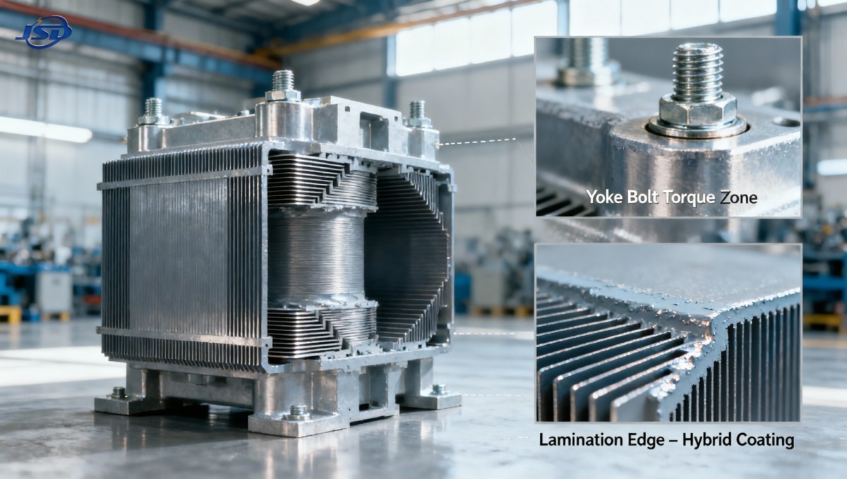
Ultimately, voltage sags do not inherently degrade low loss transformer core laminations faster—but their repetition, especially under specific timing, sequence, and system-response conditions, enables secondary degradation pathways that standard aging models overlook. Recognizing these pathways—thermal fatigue at insulation interfaces, mechanical resonance from recovery transients, and localized saturation from remanent flux interaction—allows targeted inspection, informed material selection, and smarter system integration. That precision separates predictive maintenance from reactive replacement.

Get a Quote
Regardless of whether you require general advice or specific support, we are happy to help you.
Send Us Your Inquiry Today

Jinshida Electric remains committed to contributing to global energy development through professional manufacturing and superior service.