





Does electric arc furnace transformer need separate neutral grounding for fault protection?
For operators managing electric arc furnace (EAF) systems, the question of whether an electric arc furnace transformer requires a separate neutral grounding connection for fault protection arises frequently—not as theoretical speculation, but during commissioning, relay coordination reviews, or after repeated nuisance tripping under unbalanced load conditions. Unlike standard distribution transformers, EAF transformers operate under highly dynamic, asymmetric, and harmonically rich electrical stresses. Ground-fault currents can behave unpredictably when the neutral point is left floating, solidly grounded, or impedance-grounded—especially during electrode sticking, arc extinction, or slag breakdown events. The core issue isn’t whether grounding *can* be done, but whether a dedicated, low-impedance neutral-to-ground path improves fault detection sensitivity, limits transient overvoltages, and maintains arc stability without compromising system selectivity or equipment insulation integrity.
The short answer is: Yes—under most industrial EAF configurations, a separately derived neutral grounding arrangement is not only recommended but often essential for reliable fault protection. This does not mean universal application of solid grounding; rather, it means intentional, engineered grounding—typically via a neutral grounding resistor (NGR) or grounding transformer—with coordinated relay settings. The decision hinges on three interdependent factors: the transformer winding configuration (e.g., delta–wye, wye–wye with zigzag tertiary), the grounding philosophy of the upstream medium-voltage network (e.g., resistance-grounded vs. ungrounded), and the specific requirements of the protective relay scheme (e.g., 51N, 64G, or residual current monitoring). Skipping this step—or defaulting to “no grounding because the primary is delta” —risks delayed ground-fault clearing, increased touch potential hazards, and insulation stress from resonant overvoltages.
Why Standard Assumptions Fail in EAF Applications
Many engineers assume that because the primary winding of an electric arc furnace transformer is typically delta-connected, no neutral grounding is needed. While technically true for zero-sequence current flow on the primary side, this overlooks two critical realities. First, the secondary is almost always wye-connected to supply the furnace electrodes—and that wye point becomes the de facto source of ground-fault current paths. Second, EAF operations generate intense third-harmonic currents and intermittent high-frequency transients. In an ungrounded or high-impedance grounded secondary, these can excite ferroresonance between transformer magnetizing inductance and system capacitance, leading to sustained overvoltages exceeding 3.0 p.u. Such overvoltages degrade bushing insulation, accelerate cable aging, and increase flashover risk at electrode holders or tap changers.
Moreover, modern EAF plants increasingly integrate auxiliary systems—like cooling pumps, dust extraction fans, and PLC-controlled electrode regulators—that share the same secondary bus. A single-phase-to-ground fault in one of those circuits may draw minimal current if the neutral is ungrounded, evading detection by overcurrent relays yet still posing shock and fire hazards. Ground-fault protection relying solely on residual current devices (RCDs) or frame leakage monitoring becomes unreliable without a defined return path.
IEC and IEEE Guidance: Not Prescriptive, But Directional
Neither IEC 60076 nor IEEE C57.109 mandates a specific neutral grounding method for furnace transformers. Instead, both standards emphasize system-level coordination. IEC 60364-4-41 requires automatic disconnection within specified time/current thresholds for faults involving exposed conductive parts—a requirement difficult to meet without a low-impedance ground reference. IEEE C57.104 recommends evaluating neutral grounding based on maximum allowable ground-fault current, transient overvoltage limits (typically ≤2.5 p.u.), and relay sensitivity. For EAF transformers rated above 20 MVA, IEEE C57.109 Annex D explicitly advises using a neutral grounding resistor sized to limit ground-fault current to 200–800 A—enough to ensure relay pickup but low enough to avoid excessive thermal stress on windings during sustained faults.
Crucially, both standards treat the transformer not as an isolated component, but as part of a larger earthing system. That includes grounding electrodes, bonding conductors, and the grounding strategy of connected switchgear. For instance, if the EAF transformer feeds into a metal-clad switchboard with integrated ground-fault sensing, the neutral grounding must align with the board’s internal CT configuration—otherwise, relay misoperation is likely.
Practical Implementation: What Operators Should Verify
Before energizing or modifying an EAF transformer installation, operators should confirm the following:
- Neutral point accessibility: Is the wye-point physically accessible and rated for continuous grounding duty? Some older furnace transformers embed the neutral internally without external terminals—requiring retrofitting or use of a grounding transformer.
- Grounding impedance value: If using an NGR, verify its resistance rating matches the system X₀/X₁ ratio and relay pickup settings. A common error is selecting an NGR based on nominal kVA instead of actual zero-sequence impedance of the downstream circuit.
- Relay coordination: Confirm that 51N (neutral overcurrent) and 64G (ground-fault) elements are enabled, calibrated, and tested—not just installed. Their time-current curves must clear downstream faults before upstream breakers operate.
- Insulation coordination: Check that BIL (Basic Insulation Level) ratings account for expected switching surges *with* grounding applied. Ungrounded operation may inflate temporary overvoltage margins on paper—but real-world EAF transients invalidate those assumptions.
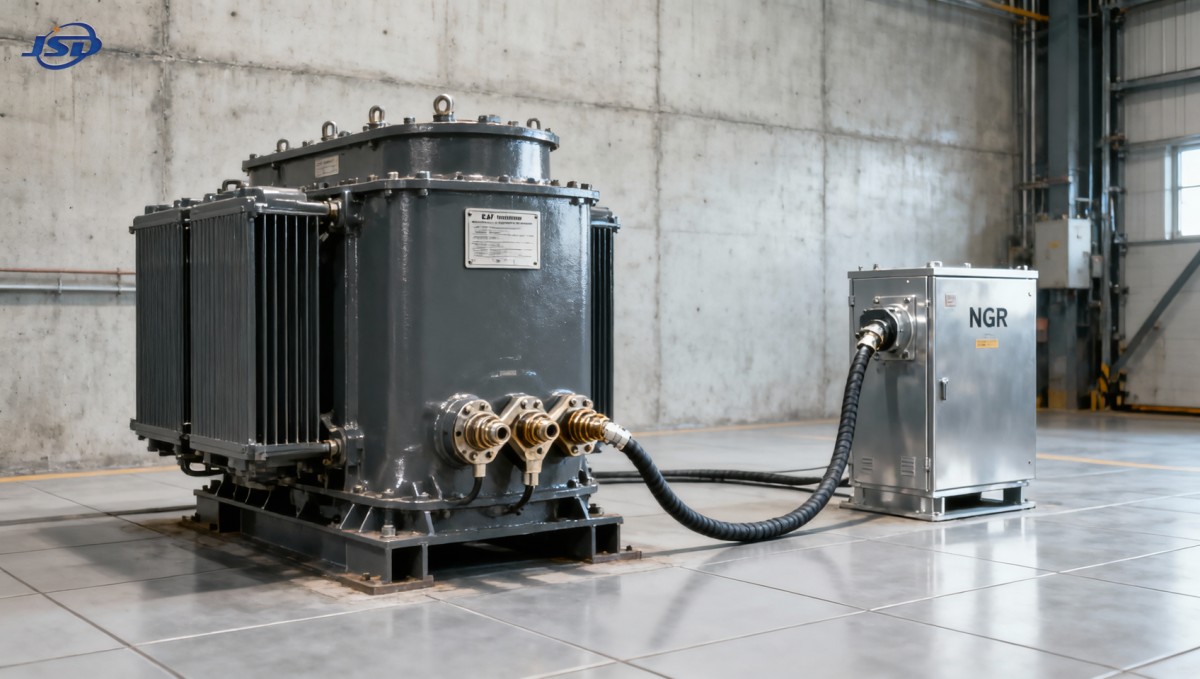
When a Pad-Mounted Solution Supports Reliable Grounding Strategy
In distributed EAF auxiliary power networks—such as those feeding electrode positioning drives, refractory cooling units, or fume extraction systems—a robust, self-contained grounding infrastructure is equally vital. For such applications, compact, pre-engineered substations eliminate field wiring uncertainties. The American-Type Pad-Mounted Substation offers IP54-rated enclosure integrity, factory-tested neutral grounding provisions, and built-in metering/monitoring interfaces compatible with EAF plant SCADA systems. Its UL- and IEEE C57-compliant design ensures consistent neutral-to-ground bonding performance across ambient temperature swings and mechanical vibration—critical where auxiliary feeders run parallel to furnace bus ducts.
Final Validation Step: Don’t Rely on Theory Alone
No grounding configuration is fully validated until measured. After installation, perform a low-voltage injection test: apply 10–50 V AC between neutral and ground, measure resulting current, and verify it aligns with calculated NGR value (±10%). Then, under controlled partial-load conditions, monitor third-harmonic content on all three phases and neutral using a power quality analyzer. A healthy, well-grounded system shows neutral current near 3× the third-harmonic phase current—confirming zero-sequence path continuity. Absence of neutral current under harmonic-rich load strongly indicates an open or high-resistance neutral bond, even if visual inspection suggests otherwise.
This verification bridges the gap between specification and operation. It transforms grounding from a static design choice into a live, measurable parameter—directly supporting the operator’s daily responsibility: maintaining arc stability while ensuring personnel safety and equipment longevity.

Get a Quote
Regardless of whether you require general advice or specific support, we are happy to help you.
Send Us Your Inquiry Today

Jinshida Electric remains committed to contributing to global energy development through professional manufacturing and superior service.