





Automatic Voltage Regulation for Substations with Variable Grid Loads
Variable loading does not automatically require a voltage-regulation system, but repeated or operationally significant voltage deviation does. The central question is whether the substation can hold the voltage at the point that matters while load, feeder current, reactive power flow, and upstream supply conditions change. A transformer nameplate ratio alone cannot do this during service. Reliable automatic voltage regulation requires a controllable voltage-changing device, suitable sensing points, and control settings that respond to real operating conditions rather than every short-lived disturbance.
For an 11 kV/0.4 kV distribution substation, the effect is familiar: as a large motor group starts, welding loads cycle, process equipment changes state, or distributed generation output shifts, the low-voltage bus may move outside its preferred operating band. The impact may include motor torque reduction, contactor dropout, nuisance alarms, poor lighting performance, unstable electronic loads, and higher current for equipment attempting to maintain power. The correct response is not simply to set a higher transformer secondary voltage. It is to determine what is moving the voltage, where the deviation occurs, and whether automatic control can correct it without creating excessive switching or masking a network problem.
Voltage variation begins with system impedance and load behavior
Voltage at a substation bus is affected by the source voltage and by the voltage drop across transformers, cables, overhead lines, switchgear, and connections. When current rises, the voltage drop across this impedance rises as well. The reactive component of current is especially important: a load with poor power factor can produce a materially different voltage effect from another load drawing the same kW.
In a simple approximation, the voltage drop on a three-phase feeder is influenced by both resistance and reactance:
ΔV ≈ √3 × I × (R cos φ + X sin φ)
This relationship explains why automatic voltage regulation cannot be separated from reactive-power behavior. A substation may experience a voltage problem during peak loading because current is high, but the same bus may rise in voltage at light load when capacitors remain connected or when embedded generation exports reactive power. A control scheme that only responds to voltage magnitude, without appropriate delay, deadband, and reactive-power coordination, can chase normal operating changes instead of regulating them.
The physical location of the complaint also matters. If the transformer secondary terminals remain near target voltage while an end-of-feeder motor panel is low, adjusting the transformer may improve one condition while overvolting loads close to the substation. Conversely, a busbar measurement may appear satisfactory even when voltage quality at a critical remote load is unacceptable. This is why voltage-regulator settings should follow the protected point of the system, not only the most convenient measurement point.
What automatic voltage regulation actually consists of
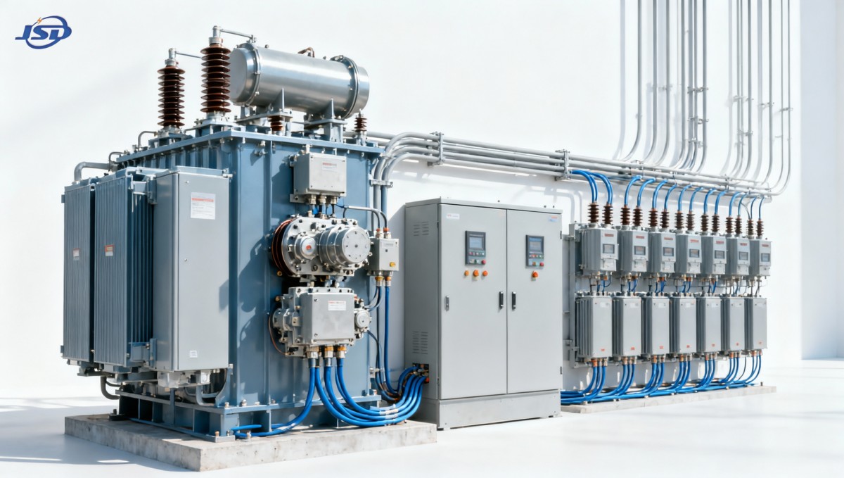
A substation transformer with automatic voltage regulation is not defined merely by having tap positions. It normally combines an on-load tap changer (OLTC), a motor-drive mechanism, an automatic voltage regulator relay or controller, voltage and current transformers for measurement, and interlocks that keep operation within safe limits. The controller compares measured voltage with a target value and commands tap movement when the deviation exceeds the configured deadband for longer than the programmed time delay.
Each part has a distinct purpose:
- OLTC: changes the effective transformer turns ratio while energized and carrying load. It is the element that provides operational voltage correction.
- Voltage measurement: provides the control input. Measurement must be correctly phased, scaled, protected, and representative of the desired regulated bus or feeder point.
- Current measurement and line-drop compensation: allow the controller to estimate voltage beyond the substation bus where feeder drop is significant.
- Deadband and time delay: prevent unnecessary tap operations caused by minor fluctuations, switching transients, and brief motor starts.
- Tap limits and alarms: prevent the control system from continuously driving toward an unattainable target when an upstream or downstream fault exists.
An off-circuit tap changer is different. It offers fixed ratio adjustment only after the transformer is isolated and de-energized. This is valuable for matching a transformer to the prevailing grid voltage during commissioning or after a planned network change, but it does not provide automatic regulation under changing load. Confusing off-circuit taps with OLTC capability is one of the most consequential specification errors in distribution projects.
For example, the 11kV Three-Phase Cast Resin Dry-Type Distribution Transformer is specified with no-load high-voltage tap ranges, depending on configuration. Those taps support planned ratio selection; they should not be interpreted as automatic, on-load voltage control. In a facility requiring continuous correction during operation, the transformer arrangement and regulator equipment must be specified accordingly.
Choosing the controlled voltage point
The regulated voltage target should be selected from the operating requirement, not copied from a generic controller setting. In a compact substation serving concentrated loads near the transformer, low-voltage bus regulation may be sufficient. In a long industrial distribution system, the key issue may be voltage at a remote motor control center, pumping station, or production line. Line-drop compensation can be used where a separate remote measurement channel is not available, but it must be based on credible feeder impedance values and expected power-factor conditions.
Line-drop compensation is not a substitute for understanding the feeder. If resistance and reactance settings are overstated, the controller may raise transformer voltage too far during high load. If they are understated, remote loads remain undervoltage while the bus appears normal. Changes in cable routes, parallel feeders, power-factor correction, or generation connections can invalidate settings that once appeared satisfactory.
Remote voltage sensing can be more direct for a critical load, but it introduces communications, measurement reliability, and fail-safe considerations. Loss of the remote signal must produce a defined response: hold the tap position, revert to local bus regulation, block automatic operation, or alarm for operator action. The selected fallback mode should match the consequence of a wrong voltage correction in that installation.
Control settings that avoid unnecessary tap wear
Automatic regulation is a controlled compromise between voltage accuracy and mechanical duty. A very narrow deadband can maintain a tightly controlled voltage, but it can also force frequent tap operations when the load naturally oscillates. A long time delay reduces operations, yet it can leave sensitive loads outside their acceptable voltage range for too long. Neither setting is universally correct.
Settings need to consider the magnitude, duration, and repetition rate of the variation. A large motor start lasting several seconds should not necessarily trigger a tap movement, especially if the voltage recovers immediately after acceleration. A sustained shift caused by a production line entering normal operation may justify a correction. Similarly, short photovoltaic output variations or capacitor-bank switching events should not cause repeated opposing tap commands.
Practical control arrangements usually include a voltage setpoint, a deadband, intentional time delay, tap-change operation limits, high/low voltage alarms, and limits for maximum and minimum tap positions. Where parallel transformers operate on the same bus, an additional coordination method is essential. Without it, one unit can raise while another lowers, creating circulating current and needless mechanical operation. Master-follower, circulating-current compensation, or other approved parallel-control functions may be used, but their application depends on transformer ratios, impedance, vector groups, control hardware, and operating philosophy.
Tap position is also diagnostic information. A transformer that spends long periods at a tap limit is not “well regulated”; it may be signaling an upstream voltage issue, incorrect nominal ratio, excessive feeder drop, unexpected reactive-power flow, or an unrealistic control target. Repeated tap hunting near the setpoint often points to a deadband or delay problem, inaccurate sensing, poor compensation settings, or a rapidly changing network condition beyond the regulator’s intended duty.
Where voltage regulation helps—and where it does not
Automatic transformer regulation is effective for relatively gradual, sustained voltage changes within the available tap range. It is not designed to solve every power-quality event. An OLTC cannot correct high-frequency harmonics, fast voltage flicker, short interruptions, severe voltage sags from faults, transient overvoltages, phase imbalance, or waveform distortion. Those conditions may require feeder reinforcement, reactive compensation, harmonic filtering, dynamic voltage-restoration equipment, UPS support, motor-starting measures, or changes to protection and network configuration.
This distinction is especially important in installations with large variable-speed drives, arc-producing loads, frequent direct-on-line motor starts, or rapidly changing converter-based generation. If voltage movement occurs faster than a tap changer can safely and appropriately respond, using the OLTC as the primary remedy will produce disappointing results and possibly excessive maintenance demand. The operator should distinguish between a sustained voltage shift and a transient event before concluding that regulator settings are at fault.
Power-factor correction must be coordinated with voltage regulation. Capacitor banks reduce reactive current and can reduce feeder voltage drop during load periods. However, switching capacitors at light load can raise voltage. If capacitor-bank and tap controls act independently with overlapping thresholds, they can create a cycle: the capacitor raises voltage, the tap changer lowers it, the capacitor drops out, and the tap changer raises again. Appropriate voltage thresholds, time delays, switching priorities, and where relevant reactive-power or power-factor controls reduce this risk.
Operating checks after commissioning
Commissioning should establish more than the correct nominal secondary voltage. Operators need a reference record of source voltage, transformer tap position, low-voltage bus voltage, feeder current, power factor, and load condition. These values allow later deviations to be interpreted rather than guessed at. A controller setpoint that seems correct in a lightly loaded test may be unsuitable when the normal process load is present.
Routine operating review should focus on trends rather than isolated readings:
- Compare bus voltage and, where applicable, remote feeder voltage across low, normal, and peak load periods.
- Review tap position movement and operation count against changes in load and source voltage.
- Check whether high- or low-voltage alarms correspond to genuine system conditions or faulty sensing.
- Confirm current-transformer and voltage-transformer circuits remain correctly connected, correctly phased, and within their intended measurement range.
- Investigate persistent operation near tap limits before changing the voltage setpoint.
- Record capacitor-bank status, generator operating state, and major load changes when abnormal regulation behavior occurs.
Mechanical and electrical condition should not be overlooked. OLTCs and their motor drives require maintenance according to the equipment manufacturer’s instructions. Abnormal motor run time, failed tap-position indication, repeated control alarms, unexpected operation counts, or disagreement between indicated and measured voltage require investigation. Blocking automatic mode without establishing a stable manual operating position can transfer the problem to the next load change.
Transformer selection must match the regulation architecture
In indoor urban and industrial distribution systems, cast-resin dry-type transformers are often selected for fire-performance and maintenance considerations. Their suitability for the location does not, by itself, determine the voltage-control method. The transformer’s voltage ratio, impedance, tap arrangement, thermal capability, protection interface, and compatibility with the wider LV system must be assessed alongside the regulation requirement.
A dry-type unit with an 11 kV primary and 0.4 kV secondary, such as the SCB10-12 configuration, can serve the common step-down duty in an 11 kV distribution network. Its listed capacities extend across a broad distribution range, and its stated temperature protection and control provisions can support safe thermal supervision. Yet thermal monitoring and voltage regulation are separate functions. Temperature sensors protect the transformer from overheating; they do not correct voltage deviation. Likewise, a forced-air overload capability should not be treated as a permanent solution to voltage drop caused by undersized feeders or excessive reactive current.
Before modifying an existing installation, confirm whether its transformer uses off-circuit taps or has an OLTC, whether the control cubicle has a functioning automatic voltage regulator, and whether the protection scheme permits the intended operating range. Review short-circuit duties and coordination as well. A tap change alters voltage level and can alter fault current on the low-voltage side, which may affect protection margins in systems already close to equipment ratings.
A stable voltage target is an operating discipline
Effective automatic voltage regulation comes from matching the control method to the behavior of the network. The best result is not the highest possible secondary voltage or the most frequent tap action. It is a stable, defensible voltage at the required point, achieved within equipment limits and without creating avoidable wear, circulating current, or conflicts with reactive-power equipment.
When loads vary, the first operating task is to separate sustained voltage deviation from transient power-quality events. Then verify the measurement point, available tap range, control settings, feeder impedance assumptions, and interaction with capacitors, generators, and parallel transformers. That sequence prevents a common mistake: treating a network-design, reactive-power, or load-starting problem as though it could always be solved by changing a transformer tap.

Get a Quote
Regardless of whether you require general advice or specific support, we are happy to help you.
Send Us Your Inquiry Today

Jinshida Electric remains committed to contributing to global energy development through professional manufacturing and superior service.