





220 kV Power Transformer Delivery: Route Surveys and Site Assembly Planning
A 220 kV power transformer should leave the factory only when its transport configuration, delivery route, unloading method, and assembly area are compatible. A road may accommodate the loaded trailer while the substation entrance cannot. A crane may have sufficient nominal capacity while lacking the reach or ground support needed at the actual unloading position. These mismatches can leave an expensive shipment waiting outside an otherwise completed site.
Plan delivery backward from the transformer’s final position on its foundation. Establish how it will be unloaded, moved into place, assembled, and preserved before selecting the transport arrangement. This connects the route survey to the installation schedule and exposes constraints while there is still time to change the plan.
Start with the shipping configuration, not the voltage rating
The designation “220 kV” does not establish transport weight or dimensions. Those depend on the transformer’s power rating, design, accessories, and shipping condition. A logistics quotation based on a similar unit can therefore be misleading.
Obtain a manufacturer-approved transport drawing and shipping schedule covering:
- Main tank shipping dimensions, mass, and center of gravity.
- Shipping condition, including oil level or specified dry-gas preservation arrangement.
- Approved lifting, jacking, pulling, support, and restraint points.
- Transport orientation and handling restrictions.
- Separate packages for bushings, radiators, conservator, cooling equipment, and other removed accessories.
- Preservation requirements, monitoring arrangements, and receipt inspection instructions.
Use shipping mass for transport calculations and the relevant handling mass for each unloading operation. The completed operating mass belongs in foundation design checks. Mixing these values can produce an unsuitable trailer arrangement or an incomplete civil assessment.
Removing accessories may reduce the transport envelope, but it creates additional site work. More joints must be assembled, components need protected storage, and lifting equipment may be required for longer. The manufacturer should define the approved disassembly scope; route constraints should not lead to improvised changes at dispatch.
Make the route survey answer specific engineering questions
A useful transformer route survey produces a documented transport plan with measured constraints and assigned actions. Driving the route and photographing narrow sections is only the starting point. The assessment must use the proposed tractor, trailer, axle arrangement, and loaded dimensions.
Can the route carry the actual load arrangement?
Bridge suitability depends on how the load reaches the structure, including axle loads, axle spacing, and vehicle position. Gross shipment weight alone is insufficient. Culverts, buried services, weak shoulders, and temporary access roads also require attention because they may carry concentrated loads poorly even when the surface appears sound.
Where a crossing needs structural assessment, obtain an engineered crossing arrangement and the necessary authorization. Adding trailer axles can improve load distribution, but it also changes vehicle length, steering behavior, and maneuvering requirements. Every proposed improvement must be checked against the remaining route constraints.
Will the complete vehicle fit through the route?
Measure loaded height from the road surface, including the trailer deck and transport supports. Check overhead structures, cables, gantries, trees, and temporary works. Clearance planning should account for road camber, suspension movement, and uneven surfaces rather than relying on a nominal height comparison.
Overhead electrical lines require coordination with the line owner. Physical clearance is only one part of the assessment; electrical approach restrictions may require a controlled outage or another approved arrangement. The haulage crew should not be expected to resolve this on arrival.
At bends and junctions, assess the swept path of the complete vehicle. Trailer wheels can cut inside the tractor’s path while parts of the load extend outward. Gateposts, drainage channels, barriers, and parked vehicles may obstruct a maneuver even where the road seems wide enough. Steep transitions also need examination because the trailer underside can contact the ground at a crest or ramp.
Can the journey be executed within the available window?
The route plan should identify permits, escorts, utility interventions, traffic restrictions, staging areas, and suitable places for emergency stops. For journeys involving ports, check berth access, transfer equipment, storage arrangements, and responsibility for each handling operation.
Record the survey date and define which changes require a fresh inspection. Roadworks, resurfacing, temporary cables, and construction activity can invalidate an earlier assessment. Recheck critical locations before dispatch, especially where the original clearance or maneuvering margin was limited.
The final approach often determines the unloading method
Survey the route from the public road through the site gate to the unloading position and foundation. Include the trailer’s departure path. A vehicle that can enter under guidance may have no practical way to turn or reverse out after unloading.
Show the proposed vehicle position, crane or gantry footprint, outrigger locations, movement corridor, accessory storage area, and exclusion zone on one coordinated site drawing. Include trenches, underground services, drainage structures, nearby energized equipment, and other contractors’ work areas.
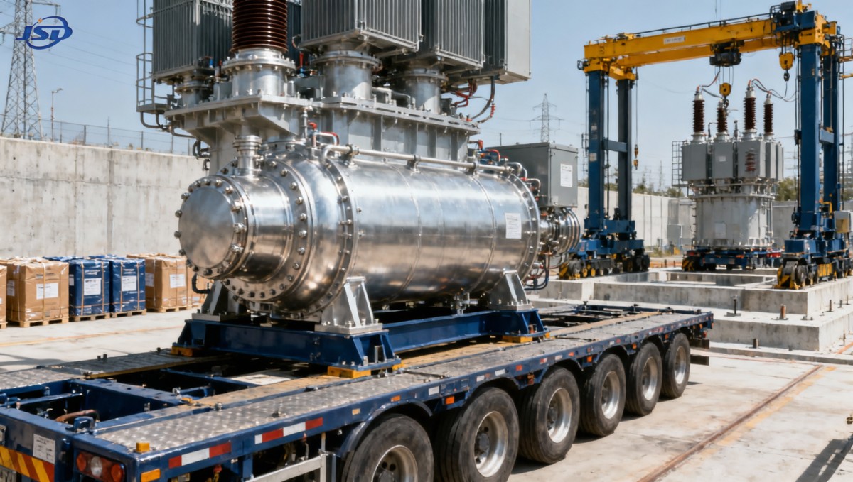
The foundation and adjacent ground perform different jobs. A foundation designed for the transformer’s operating load does not automatically support crane outriggers or temporary skidding equipment. Ground assessments must consider the concentrated reactions from the selected handling method, with suitable mats or engineered supports where required.
Temporary roads also need drainage and weather planning. A surface that supports routine construction traffic in dry conditions may deteriorate before a heavy delivery. Define inspection and repair responsibilities, along with an alternative holding location if site access becomes unsuitable.
Choose unloading equipment around the actual geometry
Mobile cranes, hydraulic gantries, and jack-and-slide systems can all be suitable, but their usefulness depends on available space, load characteristics, and the route to the foundation. Select the method through an engineered handling plan.
A crane’s advertised capacity is not its capacity at every working radius. Check the complete lift, including the furthest load position, rigging, and any restrictions imposed by the selected configuration. Where more than one lifting device is involved, load sharing and movement coordination require specific engineering.
Use only manufacturer-approved handling points. Connections suitable for securing the transformer during transport may not be lifting points. Rigging geometry must also protect the tank and fittings from unintended side loads.
Before handling begins, agree the communication method, exclusion zone, weather limits, stop conditions, and response to equipment failure. The trailer should be released only after the transformer is securely supported and the unloading operation has been accepted.
Prepare the assembly area before the main tank arrives
Delivery planning must include the components that travel separately. If the main tank blocks the only access corridor, later deliveries of radiators or bushings may become difficult. Sequence shipments and storage positions around the assembly order.
Bushings need handling and storage arrangements that protect their insulation surfaces and follow the manufacturer’s orientation requirements. Radiators and pipework need clean, protected connections. Keep labels and package references intact so that the assembly crew can match each item to the drawings without opening every package.
Agree the receipt procedure in advance. Check package condition, seals, visible damage, preservation indicators, and shock-recorder information where fitted. Photograph discrepancies before unloading or unpacking obscures the evidence. A recorder alarm calls for assessment under the agreed acceptance procedure; it does not by itself prove internal damage.
Site assembly readiness should cover tools, lifting accessories, gaskets, consumables, oil-handling equipment, clean hoses, spill control, and competent personnel. Establish how open connections will be protected from moisture and contamination, and what happens if weather interrupts the work.
Vacuum treatment and oil filling must follow the transformer manufacturer’s procedure. Tank capability and the permitted condition of connected accessories matter; not every component can remain exposed to every vacuum operation. Set the sequence, limits, and acceptance criteria before equipment mobilization.
If assembly is delayed, preservation becomes a scheduled activity. Assign responsibility for monitoring the specified shipping condition, protecting accessories, and recording inspections. An unloaded transformer can still suffer deterioration while waiting for installation.
Temporary power must match the assembly workload
An unfinished substation may lack a dependable construction supply when installation begins. List the loads that will operate together, including lighting, communication equipment, tools, pumps, and oil-processing equipment. Check voltage, frequency, starting demand, earthing, protection, and required operating duration.
For suitable temporary loads, the 50kW/100kWh Portable Trailer Energy Storage System provides a mobile option with LiFePO4 batteries, a 50 kW PCS, and 400 V AC output. Its relevance here is supplying compatible site services where permanent power is unavailable. Oil-processing machinery needs a separate load assessment because heaters and motors may exceed the available output or starting capability.
Power capacity and stored energy answer different questions. The kW rating limits simultaneous demand; the kWh rating influences duration. Usable operating time also depends on conversion losses, reserve settings, and the load profile. Include a recharge arrangement through a compatible grid, solar, or generator connection, and keep the trailer clear of lifting zones and transport corridors.
Use a dispatch gate that connects every contractor’s responsibilities
A delivery date becomes credible when route approval, site readiness, equipment availability, and assembly support align. Factory completion alone cannot establish that date.
Use a joint readiness review with clear evidence for each item:
- Transport data is approved: the shipping drawing, package list, handling restrictions, and preservation instructions are issued.
- The route is executable: critical crossings and clearances are resolved, with permits and interventions arranged.
- The receiving site is ready: access, foundation, temporary supports, storage, and the vehicle exit path are available.
- Unloading is prepared: the engineered method, equipment, crew, rigging, and ground support match the site layout.
- Assembly can proceed: accessories, consumables, technical supervision, temporary power, and oil-handling resources are coordinated.
- Exceptions have owners: weather disruption, transport damage, preservation concerns, and late deliveries have defined responses.
Separate “delivered,” “mechanically assembled,” and “ready for energization” in the schedule and handover documents. Mechanical completion still leaves inspection, electrical testing, protection and control checks, and agreed acceptance activities. This distinction prevents a delivery milestone from creating an unrealistic energization commitment.
The most useful next step is to place the approved shipping drawing, route survey, and unloading layout side by side. Trace the transformer’s movement from the factory to its final foundation, then trace how each accessory and assembly resource reaches it. Any unresolved transition needs an owner and a completion date before dispatch.

Get a Quote
Regardless of whether you require general advice or specific support, we are happy to help you.
Send Us Your Inquiry Today

Jinshida Electric remains committed to contributing to global energy development through professional manufacturing and superior service.